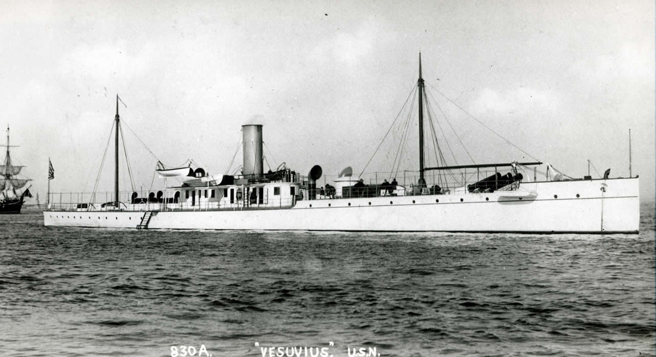
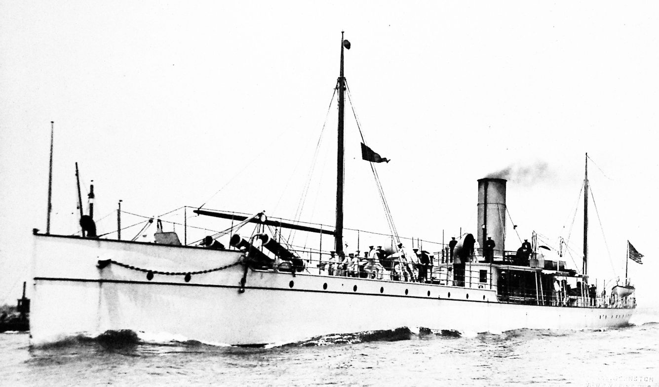
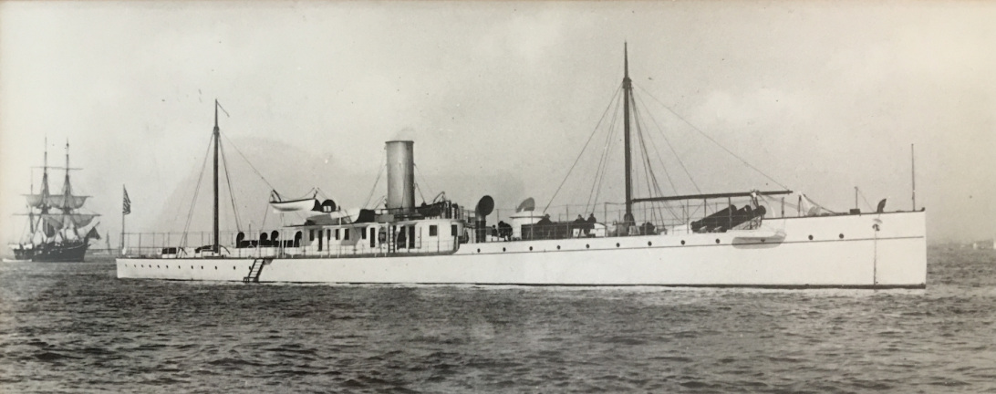
USS Vesuvius, Dynamite Cruiser of 1888
Following is information about the US Naval vessel, the Vesuvius. To go to discussion of the model of this vessel click here Some additional photos are here.
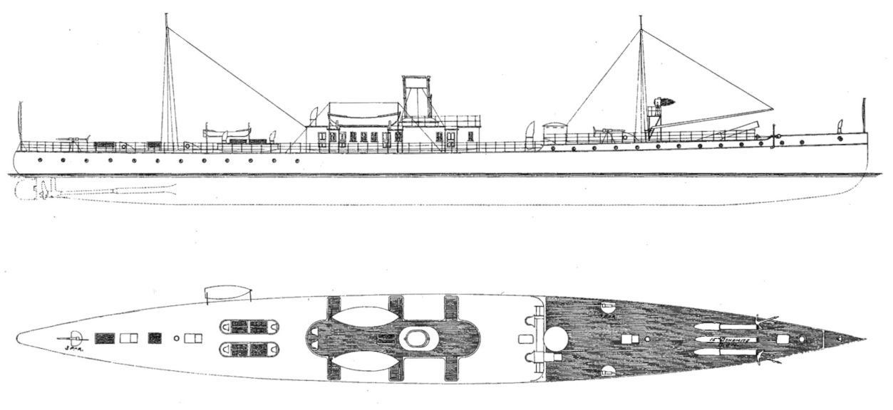
The Vesuvius of 1888 was neither a cruiser or a dynamite ship. It was an experimental steam-powered steel ship built around three pneumatic "cannon" designed to launch projectiles containing a mix of nitrocellulose and nitroglycerine, considered more stable to handle than dynamite, but still too dangerous to be fired from a conventional weapon, hence the choice of compressed air as propellant. The guns had been conceived by a D.M.Medford and the design refined by Edmund Zalinski (or Zalinsky), a retired US Army officer, who had tried for some years to interest various military organizations in their use. Finally, the US Navy bit.
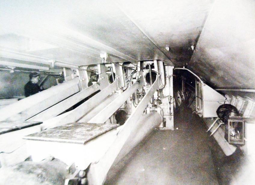
The "guns" themselves were 15 inch diameter cast iron tubes about 55 feet long. There were Three mounted in fixed position in the hull of the Vesuvius at about 16 degree elevation. About fifteen feet of the guns were exposed above the deck. At the breech end, there was machinery to handle the projectiles, tanks to hold the compressed air, and the air compressors. The projectiles fired by the guns were about seven feet long and held up to 550 pounds of the explosive mix, which could be detonated on impact, or with a timed electrical fuze. The projectiles also had small fins to cause the missile to rotate in flight for stabilization. The guns had a range of about one mile but the range could be extended by using a smaller load of explosive and could be decreased by using lower air pressure instead of the normal 1,000 psi to launch the projectile. The ship carried ten projectiles per gun.
There were several design flaws with the vessel, which was not a successful experiment.
The first was the fixed position of the main guns, which meant that they could not be elevated nor depressed to change angle of fire or range of the weapon, and the boat had to be maneuvered from side to side to aim them at all, the same problem that the much earlier "bomb vessels" had. For practical purposes, the ship had to anchor close inshore with multiple anchors and adjust the lengths of the anchor cables to change the ships position in order to aim the pneumatic cannon. This method of aiming the guns, plus the limited range, exposed the ship to surface vessel attack from shore based small vessels as well as presenting a fixed target for shore batteries.
The second flaw was that, other than the main battery, the ship was under-gunned, having only three (later five) 3-pounder guns in exposed mounts at bow and stern and along the sides. These were insufficient to counter any attack by surface vessels, even small ones. Crew members armed with small arms were also stationed along the decks, but even if these precautions were able to repel an attack by small boats, they would be ineffective against evan a lightly armed warship.
And the third defect was the hull design, long and narrow, with little freeboard. Although this gave her a profile more resembling a private yacht, it resulted in poor handling in open waters. The hull design and the powerful steam engines made her fast, so later she was used as a communication vessel and ultimately converted to an experimental torpedo boat in 1904.
Specifications:
Displacement: 945 tons
Length: 246' 3"
Breadth: 26' 6"
Armament: 3 15" pneumatic cannon, three 3-pounder guns
Complement: 70
Propulsion: two triple expansion reciprocating steam engines, twin screws
The ship was built by Wm.Cramps and Sons shipyard in Philadelphia, PA, launched in 1888 and commissioned in 1890. During sea trials, she exceeded the contract speed requirement of 20 knots by achieving 21 knots. She served with the Atlantic Fleet and during the Spanish American War, she was used as a dispatch vessel between Cuba and Florida and participated in several bombardments of Santiago, Cuba during that war. At the time, the reports of her effectivness were positive, citing the silence of the guns and the surprise effect of the sudden explosions on the populace, but naval authorities were less impressed. The aiming proved cumbersome and inaccurate and the range of the guns too short. And the ship was exposed to attack from small boats operating offshore. During one bombardment, the Vesuvius attempted a quick escape by reversing at speed and nearly drove her stern underwater.
She was converted to an experimental torpedo boat in 1904 and participated in trials of several types of torpedoes then being developed. Damaged by a circular running torpedo in 1915, she was laid up, then decommissioned in 1920 and scrapped in 1921.
I first found out about the Vesuvius in the late 1960s when on a visit to New York city with the Philadelphia Ship Model Society we visited a small shop that sold ship plans. I found there a plan from the Navy that showed the vessel before and after conversion to a torpedo boat. I was dissuaded from buying that plan because of cost and instead tried to find plans from the Cramps material stored in Philadelphia, forgetting that Cramps had not done the conversion and would not have plans for it. To my regret, I have never located plans for Vesuvius as a torpedo boat.
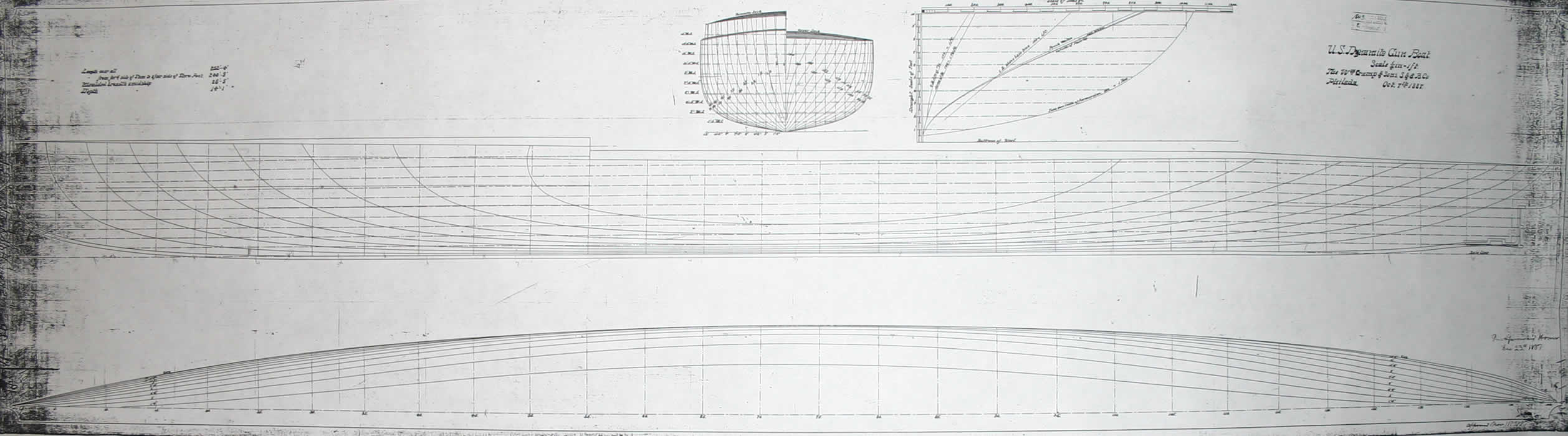
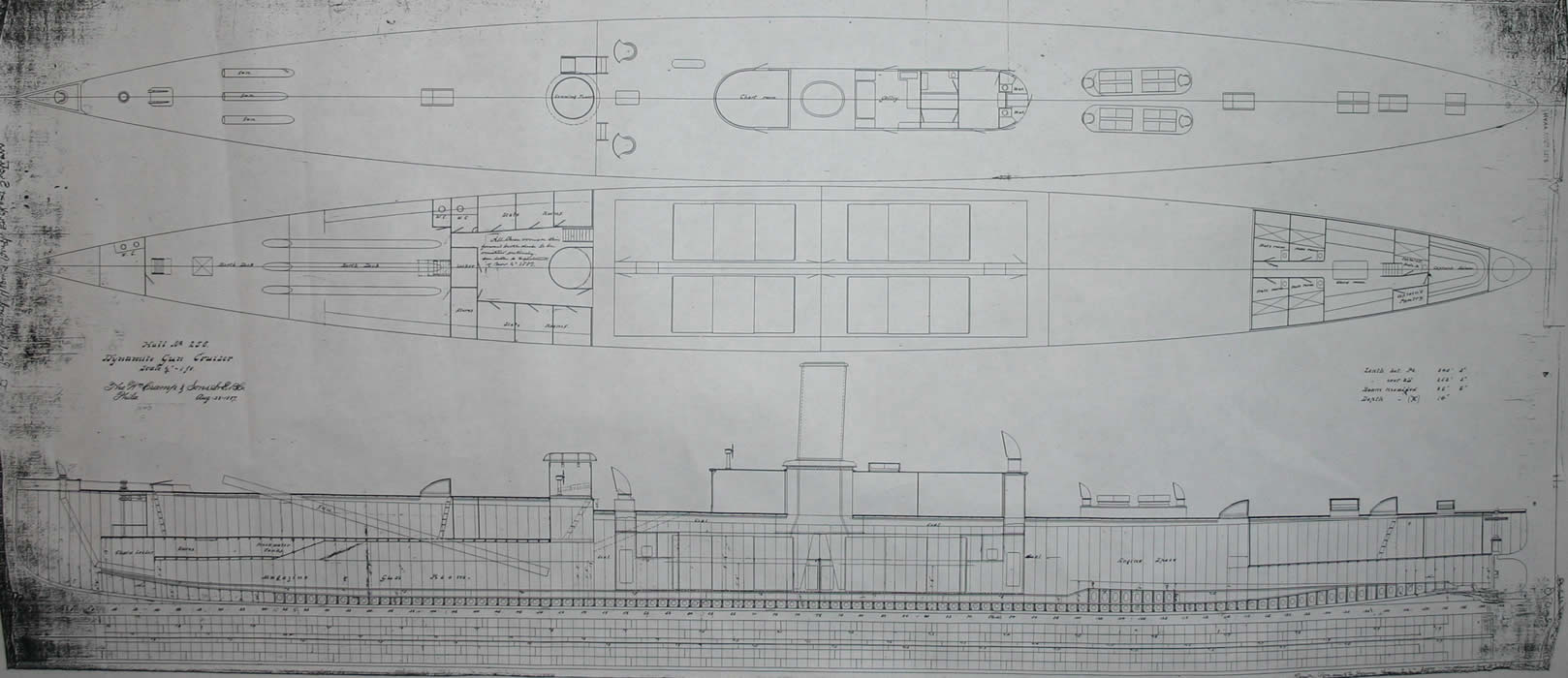
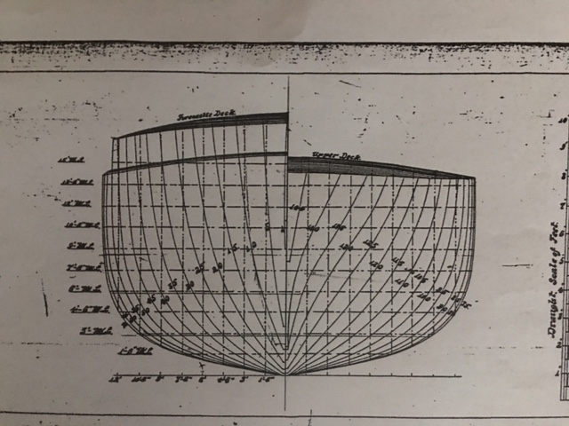
But I did finally find plans for the original ship in the "dynamite gun" configuration in the National Archives in about 1997 and planned a model in 1/8" scale I made up a solid wooden hull in pine using the bread and butter technique, but I found that scale too small for the sort of detail I like, so in 2015 I discarded the solid hull and started a new model in 1:64 (3/16") scale as a radio controlled boat. Here are some of the plans I found in the Archives and photo-reduced to my preferred scale.
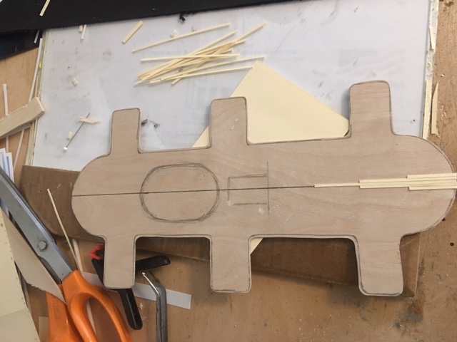
Using the drawings above as well as some additional very detailed construction and framing plans from the Archives, I finally began my Vesuvius model. The build method for the hull was pretty much my standard approach: I first made full sized copies of the profile and laid out the plan for the keel/stem/sternpost on it, marking the location of each bulkhead, corresponding to the frame stations on the plan for the frames. Because I build the hulls upside down (Hahn method) I also mark on the plans the location of the horizontal line parallel to the keel that will be the level of the building board, the reference line. I do this on the side profile when laying out the keel and on the frame station plan making certain the two correspond exactly. Then I cut the keel plan out and glue it to the plywood to be used for the framing, in this case 5/32" luan plywood, using school glue or some other water-soluable glue.
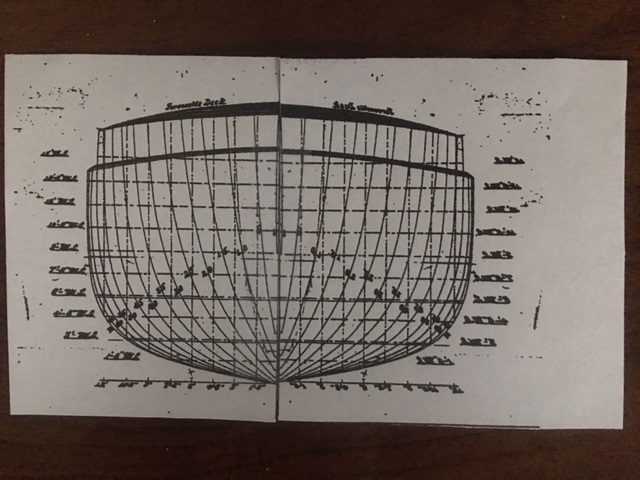
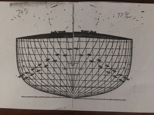
In this case, I made full size copies of the station profiles, then reversed one, so I could cut the two apart along the centerline and tape them together, joining the two forward station profile plans and the two after station profile plans to make a full-width version of the stations. Then i make multiple copies of the forward stations and of the after stations, and cut each frame out, one for each bulkhead, using one bulkhead/frame for each station. Then I draw the central cut-out before gluing the frames to the plywood. I cut the parts out using a bandsaw and/or a scroll saw.
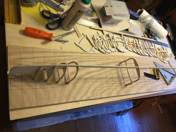
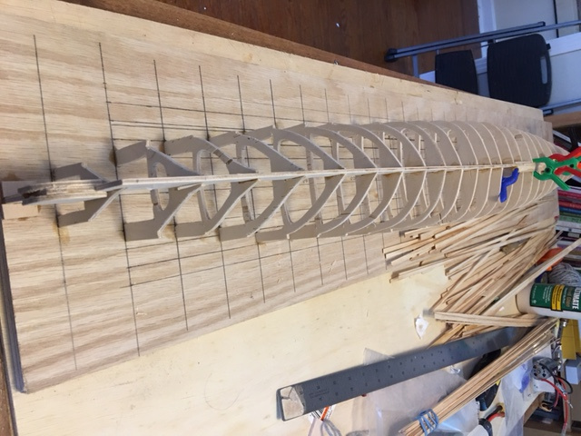
The three photos below show the process. The first shows the frame stations from the original plan. Next shows the reversed/cut apart/reassembled plan for the forward then the after frames. These last frame plans were then copied and cut out to glue to plywood and cut out the frames. In this model there were about thirty frames/bulkheads. When modeling certain hulls with this technique, it is sometimes advisable to draw soem additional frames/profiles if there are sharp curves or if you want some extra strength. It is pretty easy to interpolate the frame shape and hand draw them if they are needed.
The picture below shows the keel on the building board. When I make the board, I make it longer than the hull and use it later as the base for a cradle for the completed hull. I also lay out on the board the longitudinal center line and each station corresponding to the plan. This makes it extremely easy to align frames/bulkheads when setting them up, as each will align to a mark on the keel and a transverse line on the building board, keeping them true and plumb as they are glued up. In this picture you can easily see the layout of the marking of the building board, and the shape of the individual frames once the center part has been cut out, leaving a deck "beam" in each. These beams reinforce the frames during planking and are selectively removed in whole or in part during later stages of building.
This picture shows the set up of the frames completed. Note the sharpness of the lines and the reinforced stern, with additional plywood on each side of what will be the rudder stuffing box.
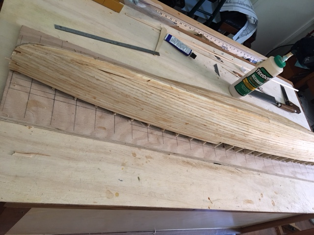
Once all the frames are glued up, the structure is very secure, strong, and easy to plank. I first sand the frame edges so the planks will run easily and true. In this model, I planked the hull with a single layer of pine planks 1/16" thick and about 3/16" wide. The original ship was a steel hull riveted to steel frames of course, but I chose to just plank the hull and finish it with multiple coats of marine spar varnish to come close to the smooth hull of the original. Later I also varnished the inside of the hull and used marine epoxy at certain areas, such as the rudder trunk and the propeller stuffing boxes, for reinforcement. If I were building this model again, I would finish the outside of the hull with epoxy also.
After varnishing the outside of the hull, I cut it free from the board at the marks denoting the top of the hull. Then I varnished the inside of the hull and did the layout of the propeller shaft stuffing boxes and the rudder trunk. This got a bit tricky, as the hull is not very deep, and the propeller shafts emerge from the hull at a pretty shallow position, so I had to plan the location of the shafts and the size and location of the gears of the drive to position the motor at the proper height to drive the gears and not protrude above the level of the top of the deck, yet to be built.
The upper picture below is a picture of the hull after planking and below that a picture of the hull cut free from the board, before trimming the frames to the level of the decks.
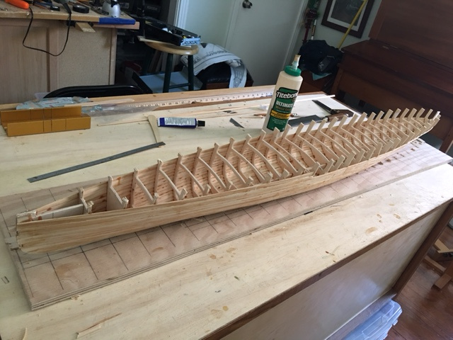
The steps outlined above took a lot of trial and error fitting and adjusting position of gear drive and motor. Once the stuffing boxes and propeller shafts were positioned, struts fabricated, propellers added, and the rudder in place, I painted the outside of the hull with white enamel and did some buoyancy testing. I was concerned that the shape of the hull would make the model unstable and likely to capsize unless I kept the center of gravity low and ballasted the model appropriately.
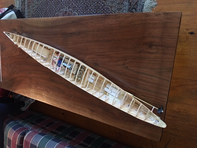
Below is a photo of the hull at this stage. Bathtub flotation testing with a battery in the battery box revealed the need for additional ballast weight to achieve floatation at the marked waterline. The round white cylinders in the contain 50 copper pennies each and are the ballast. These fit nicely and snugly between adjacent frames and could be adjusted forward and aft to achieve desired flotation at the waterline.
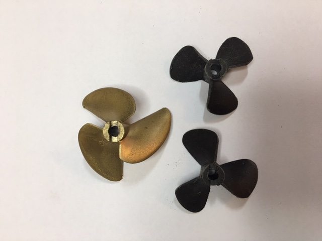
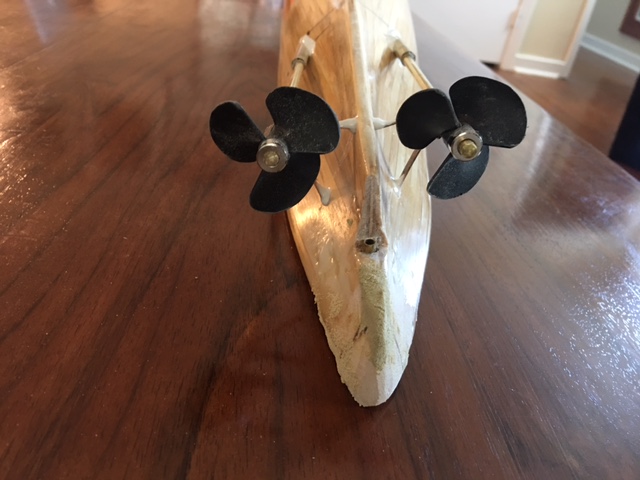
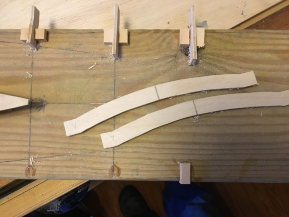
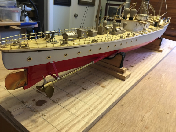
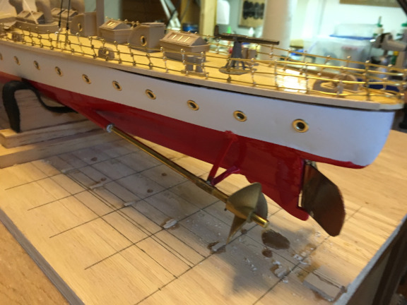
Once the propeller shafts were positioned and the struts in place, I fabricated some propellers. I started with some spare plastic props from the large PT model (Higgins PT 277) and carved and sanded the blades to more resemble what propellers of that era (1890) might have looked like. The original props were designed for speed and had modern shapes and a deep bite but modified nicely. The photos below show one of the orginal spare props (bronze painted) and two modifed props. The props are secured by a transverse pin in the shaft, so all I had to do was drill the shaft for the pin, solder it in place, then slide on the prop and secure it with a collar. The shafts are 3/16" brass and are secured on the inside by additional collars, so they can be removed easily by sliding out of the stuffing boxes. In the lower two pictures tbe original, unmodified, props are temporarily installed. You can see why I decided to modify them to more resemble older style propellers.
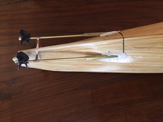
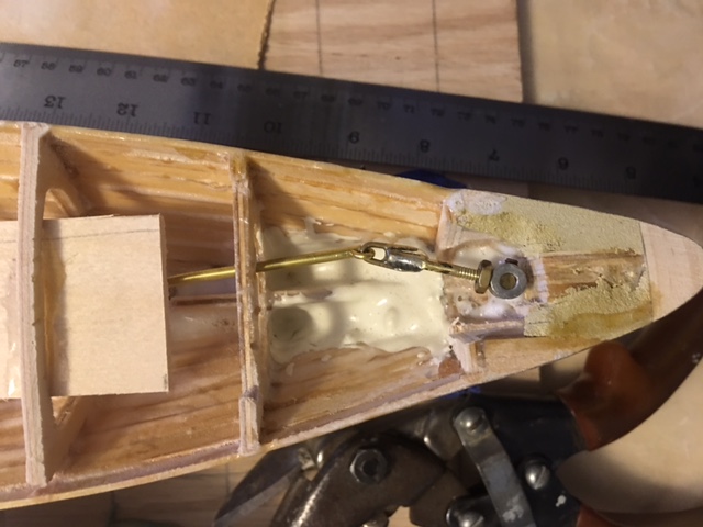
The rudder was a bit of a problem, due to the extremely narrow stern. I made up a rudder arm by drilling and tapping a collar and using a treaded brass rod in the collar, secured with a lock nut, connecting to another longer brass rod which pivots at its centerpoint in a loose fitting. The servo arm can be connected to the forward end of the longer rod and control the rudder much like the old "whipstaff" tiller in sailing ships. By making the center pivot of the longer rod very loose (a washer), and the connection to the rudder arm also loose, there was enough slack in the system to accomodate the arc of travel of the servo and of the rudder arm. Not very elegant, but it worked. If doing again, I would use a flexible shaft rudder control wire system and a short rudder arm.
Here's a picture of the rudder installation. I left the (steel) set screw in the collar on the rudder shaft for security since I did not want to use the threaded brass rod of the rudder arm as a set screw. You can see both in the photo.
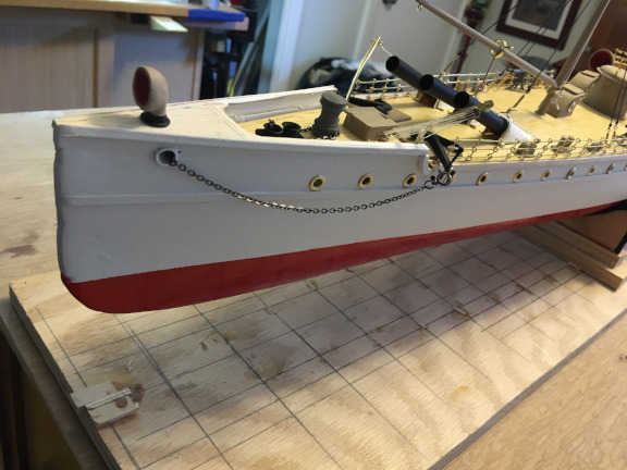
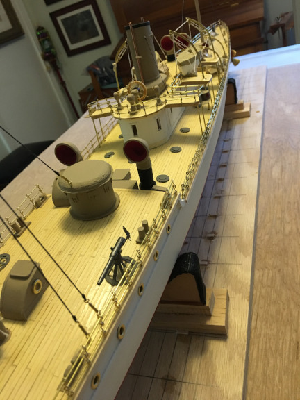
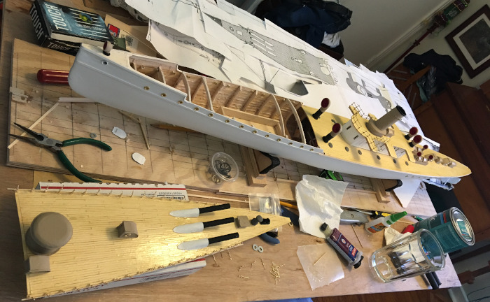
At this point, the hull was pretty much done, except for adding details such as portholes and painting the waterline. I decided to paint the model in what might have been her colors in the inter-war period. Most likely when she was on active duty during the Spanish-American War, she would have been a gray color. But perhaps before that, and certainly after, she was part of the "great white fleet" color scheme, and I thought that might make a much prettier model. So I decided on white for the hull, with red below the waterline, buff/tan for cabin and deck structure sides, gray for tops of deck structures, and black for guns and some metalwork. In another departure from authenticity, I decided to make the portholes and railing bright brass, although in the original they were painted steel. The color scheme made for an attractive, if not entirely authentic, model
I made the portholes of brass 1/4" eyelets. I placed them on waxed paper and filled the holes with fast setting epoxy. This made a transleucent and watertight glazin. I installed them after I had made and fitted the decks.
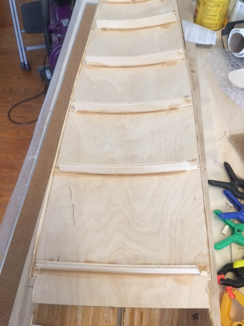
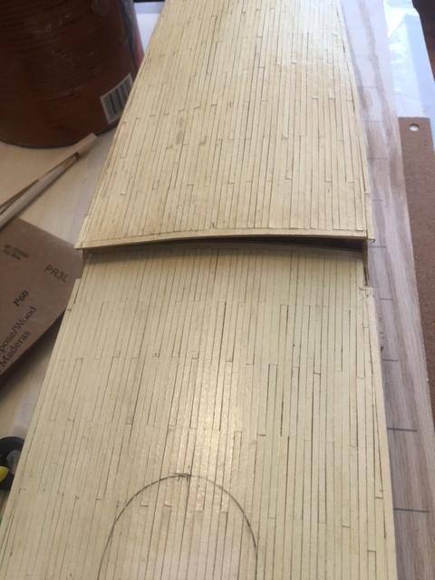
The decks are 1/32" birch plywood, planked with "planks" cut from old manila file folders, glued to the plywood, then varnished. The deck is in two parts, with the main deck sliding under the forward deck at the break in the height of deck and hull. The main deck has a cut out for the cabin as shown in the photos below, originally intended to be access to the ESC switch, by removing the cabin, but in the end, this approach wasn't needed as both decks remove easily when setting up for a run on the water, and the cabin was better off being securely fastened to the deck.
Here are some photos of how the decks were made up.
The shots below show the underside of the main deck with the formers creating the shape camber of the deck. On the right is a shot of the way the two decks look when placed on the hull. The forward deck slides beneath structures at the very front of vessel to secure it forward, then fits securely to the hull at the break. The main deck is about half an inch lower and slides under the forward deck and is secured by structures (stairways) at the forward end. I did not bother to add hold down screws to either deck as they fit pretty well, but after the sea trials (see below) I concluded that I should have done so.
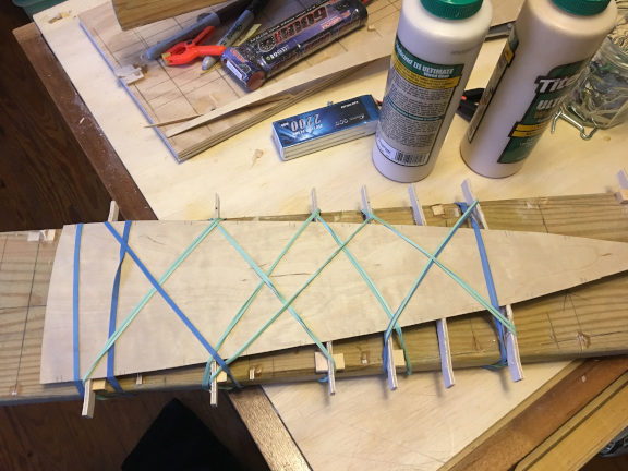
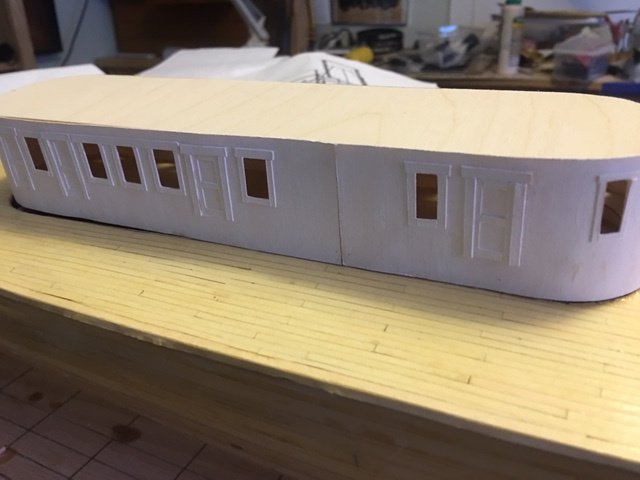
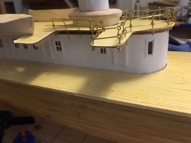
I was concerned about adding too much weight topside because of my feeling that the shape of the hull made the model inherently top heavy and likely to capsize at speed, I decided to make the cabin and other deck structures as light as possible, using thin plywood, balsa, basswood, and cardstock for most of these details. I looked into purchase of proper brass stanchions in scale for the railings, but needed about 300 of them and buying them would exceed my hobby budget for the year so I just worked them up out of brass wire. They are not very elegant, and hardly true to scale, but from a modest distance, they look fine, and the other details of the model draw the eye and attention from the deficiencies of the stanchions.
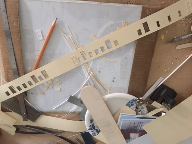
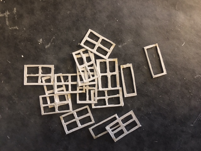
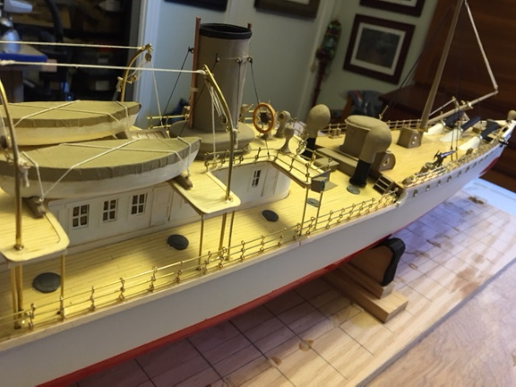
Below are some photos of the building of the cabin and other structues without much comment, as they seem pretty obvious at first look.
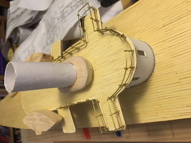
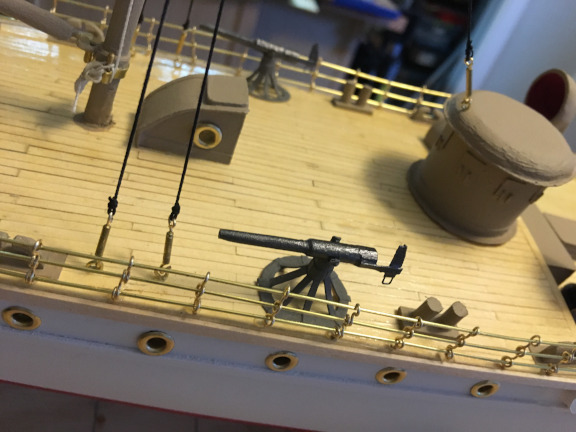
Following are photos of the completed model. I carved the ventilators from maple, built the main battery guns from aluminum tubing and the smaller guns from carved wood, paper, and wire. The engine room skylights, companionways and such were built up from balsa, plywood, and cardstock. Anchors carved from ebony. Lifeboats from pine. Capstans from maple. The anchor chain on the port side is connected to the anchor with a necklace clasp so it can be disconnected when removing the deck.

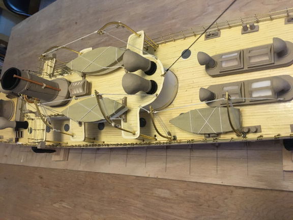
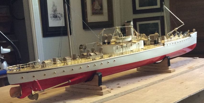
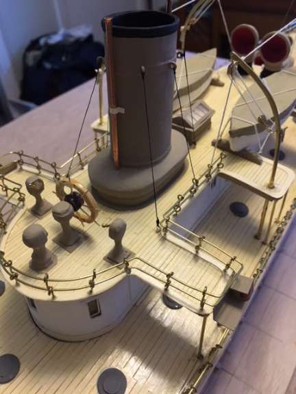
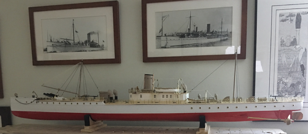
And finally a shot of the model displayed along with a few pictures of the original.
For the RC modelers, here is a picture of the model with the fore deck removed to access the battery. It is powered with a 2S LiPo battery and ESC and a brushed 540 motor driving the two screws through a gearbox assembled from Dumas gears. Note that this picture was taken before all the details of the fore deck and main deck had been completed. (railings, guns, mast, capstans, etc. etc.)
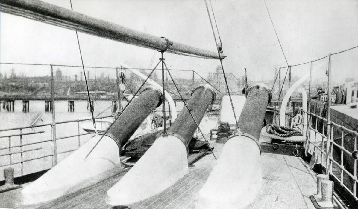
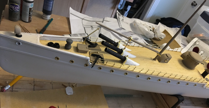
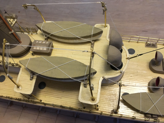
The foredeck of Vesuvius showing the three pneumatic cannon muzzles.